


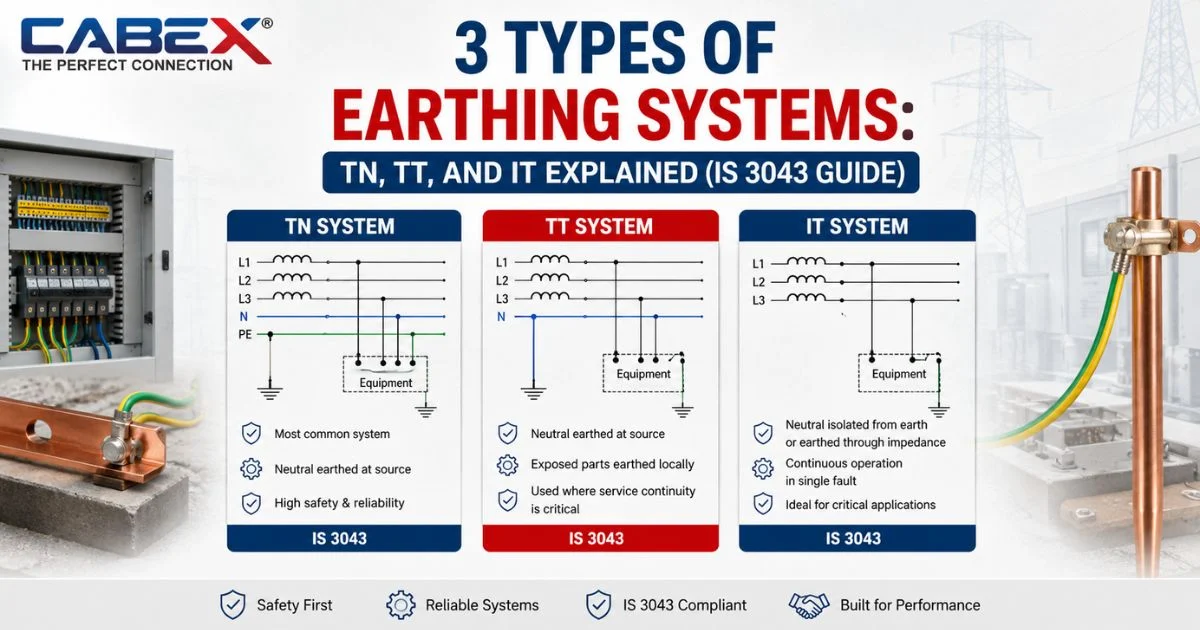
A single loose earth connection can turn a minor insulation fault into a fatal shock. That is why every electrical installation in India — from a residential flat to a Gulf-bound export panel — must follow one of three internationally recognized earthing systems.
The three types of earthing systems are TN, TT, and IT, as classified by IEC 60364 and adopted in India under IS 3043:2018. Each system defines how the supply neutral and the exposed metal parts of an installation relate to earth. Understanding this classification is the first step before you even pick electrodes, conductors, or accessories.
At Cabex India, we manufacture earthing and cable-management components used across all three configurations. This guide breaks down how each system works, where it applies, and how to stay compliant.
What Are the 3 Types of Earthing Systems?
The three types of earthing systems are TN, TT, and IT — each named for how the source and the installation connect to earth. The letters follow a fixed code: the first letter describes the source’s earth connection, and the second describes the installation’s earth connection.
T means the point is directly connected to earth. N means the exposed metal parts connect to the neutral. I means the source is isolated from earth or grounded through high impedance.
In practice, TN systems dominate urban and industrial India. TT systems appear in rural and standalone installations. IT systems serve critical, uptime-sensitive facilities such as hospitals and process plants. Each configuration changes how fault current returns to source, which in turn dictates your protective device selection.
How Does the TN Earthing System Work?
In a TN system, the source neutral connects directly to earth, and the installation’s exposed metal parts connect back to that same earthed point through a protective conductor. This creates a solid metallic fault-current path, which allows fast, predictable disconnection during a fault.
TN systems split into three variants, and this distinction matters for compliance:
| TN Variant | Neutral & Protective Conductor | Common Use in India |
| TN-S | Fully separate throughout the system | HT/LT industrial supply via captive substation |
| TN-C | Combined into a single PEN conductor | Older concentric wiring, now largely discouraged |
| TN-C-S | Combined upstream, separated at the building | Common LV commercial and domestic supply |
Furthermore, IS 3043 explicitly permits TN-C only for cross-sections above 10 mm² copper or 16 mm² aluminium, and only where no residual current device (RCD) protects that section. TN-C-S remains the most practical choice for most Indian commercial buildings because it balances cost with a genuinely low fault-loop impedance.
Because the fault path is metallic and low-resistance, TN systems typically achieve the fastest disconnection times among the three configurations. This makes TN the default recommendation wherever the supply utility already provides an earthed neutral at the point of connection.
How Does the TT Earthing System Work?
In a TT system, the supply neutral is earthed at the source, but your installation uses its own independent earth electrode — completely separate from the utility’s earth. As a result, the fault-current path runs through the soil itself rather than through a metallic conductor.
This soil-return path carries much higher impedance than a TN system. Consequently, IS 3043 and IEC 60364 both mandate residual current devices (RCDs) as the primary protection method, since standard MCBs alone often cannot detect the smaller fault currents involved.
TT is common in rural India, standalone farmhouses, telecom towers, and any site where the utility cannot guarantee a stable earthed neutral at the supply point. In particular, overhead-line rural feeders frequently use TT because the earth mass itself serves as the return path.
One practical trade-off: TT installations need periodic earth-resistance testing, since soil conditions shift with moisture and season. A pit that tests well in monsoon can show a very different reading in peak summer.
How Does the IT Earthing System Work?
An IT system either isolates the source from earth entirely or connects it through high impedance. The installation’s exposed metal parts still connect to independent earth electrodes, but no direct low-impedance path exists back to the source.
This design has one major advantage: the installation keeps running after a first insulation fault. A first fault to earth does not automatically trip the supply, because no complete low-impedance loop exists yet. That is why hospitals, mines, and continuous-process manufacturing plants often specify IT systems — unplanned downtime carries real safety and financial risk in these settings.
However, IT systems demand continuous insulation monitoring. Without an insulation monitoring device (IMD) to flag that first fault, a second fault on a different phase can create a genuinely dangerous phase-to-phase condition. For this reason, IT installations always pair with dedicated monitoring equipment, not passive protection alone.
TN vs TT vs IT: Which Earthing System Should You Choose?
Selection depends on your supply source, soil resistivity, budget, and how critical continuous operation is to your site.
| Factor | TN System | TT System | IT System |
| Fault-loop impedance | Low (metallic path) | High (soil path) | Very high (isolated/impedance-earthed) |
| Primary protection | MCB/MCCB | RCD (mandatory) | Insulation monitoring device |
| Typical application | Urban, industrial, commercial | Rural, standalone, telecom | Hospitals, mines, process plants |
| Continues after first fault? | No | No | Yes |
| Relative installation cost | Moderate | Lower | Higher (monitoring equipment) |
Notably, most Indian installations default to TN-C-S simply because utilities already provide an earthed neutral. On the other hand, sites without a reliable utility earth — or sites where uptime outweighs cost — should evaluate TT or IT on their specific risk profile.
Which Earthing System Applies Under India’s IS 3043 Standard?
India follows IS 3043:2018, the Bureau of Indian Standards’ Code of Practice for Earthing, which adopts the same TN, TT, and IT classification used internationally under IEC 60364 (BIS IS 3043:2018, Bureau of Indian Standards). This means the 3 types of earthing systems in India follow the identical technical logic used across Europe and the Gulf — a genuine advantage for exporters building panels to a single design standard.
IS 3043 also specifies the physical electrode types permitted within any of these three systems: pipe electrodes, plate electrodes, strip or wire electrodes, earth mats for substations, and concrete-encased electrodes (BIS IS 3043:2018 summary). GI pipe electrodes typically use a minimum 40 mm diameter pipe driven at least 3 metres deep, while plate electrodes use GI plates of at least 600 mm × 600 mm.
Additionally, the standard mandates the green-yellow bicolour marking as the only acceptable identification for protective conductors, regardless of which of the three systems you install. Above all, IS 3043 ties every electrode choice back to soil resistivity testing using the Wenner four-pin method, since resistivity ultimately determines whether your chosen system will actually perform as designed.
What Compliance Steps Do These Systems Share?
Regardless of which system you install, a few requirements apply across all three:
- Soil resistivity testing before electrode sizing, since resistivity varies with moisture, salt content, and soil type
- Two independent earth connections for medium and high-voltage equipment, per IS 3043
- Green-yellow bicolour marking on every protective conductor, with no other acceptable colour code
- Periodic testing of earth resistance, especially for TT installations where soil conditions shift seasonally
- Corrosion-resistant materials at every joint, since galvanic corrosion between dissimilar metals silently raises resistance over time
In short, the system you choose determines your protection strategy, but the underlying quality of your electrodes and conductors determines whether that strategy actually works in the field.
Need certified, corrosion-resistant earthing accessories that meet IS 3043 and IEC 60364 across TN, TT, or IT installations? Cabex India supplies GI and copper earthing components engineered for Indian soil conditions and Gulf export compliance alike.
Conclusion
TN, TT, and IT remain the three earthing systems recognized worldwide, and India’s IS 3043 standard applies the same logic locally. Your choice comes down to how your supply is earthed, your soil conditions, and how much downtime your site can tolerate. Getting this classification right at the design stage saves significant rework later.
Frequently Asked Questions
What are the 3 types of earthing systems?
The three types are TN, TT, and IT, classified by IEC 60364 and adopted in India through IS 3043, based on how the source and installation connect to earth.
Which earthing system is most common in India?
TN-C-S is the most common configuration in urban and commercial India, since utilities typically supply an already-earthed neutral to the building.
Is RCD compulsory in a TT earthing system?
Yes, IS 3043 and IEC 60364 both require an RCD in TT systems because the higher soil-return impedance prevents standard breakers from detecting smaller fault currents reliably.
Why do hospitals use an IT earthing system?
Hospitals use IT systems because the installation keeps running after a first insulation fault, avoiding sudden power loss during critical procedures until the fault is located and cleared.
Does IS 3043 apply to industrial and export-grade earthing in India?
Yes, IS 3043:2018 governs earthing design, installation, and testing for residential, commercial, and industrial installations across India, and it aligns with IEC 60364 for exporters building to Gulf or European specifications.
What is meant by the 3 types of earthing systems?
The 3 types of earthing systems — TN, TT, and IT — describe how the neutral and exposed metal parts of an electrical installation connect to earth, and each configuration changes which protective device (MCB, RCD, or insulation monitor) keeps the installation safe.


